Building an RF Step Attenuator
The idea was to build an RF Step Attenuator to be used for checking scope step responses using the Pulse Head of a CG501x which has a fixed amplitude output
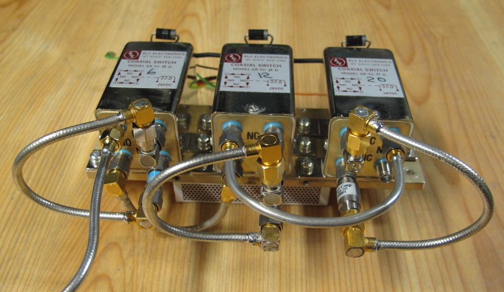
Started with three RF switches, some semi rigid coax cables and several SMA attenuators to make up 6 dB, 12 dB and 20 dB attenuation.
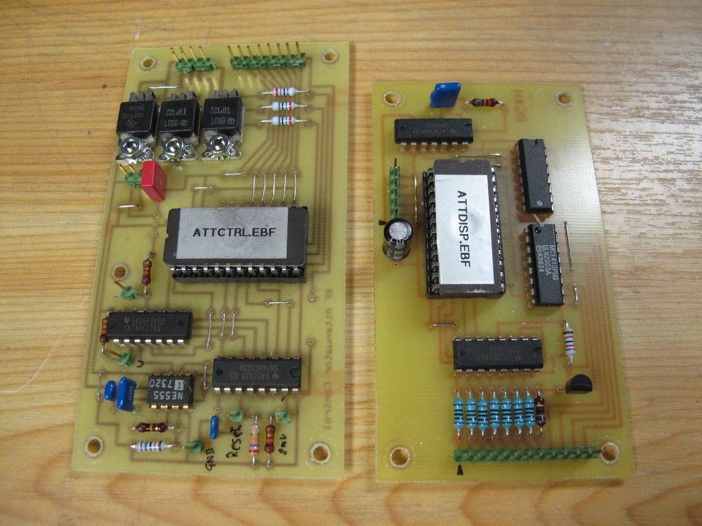
Made two special circuit boards, one to decode the push buttons and control the switches and one to drive a 7-segments display.
Schematic Control Board, Display Driver board.
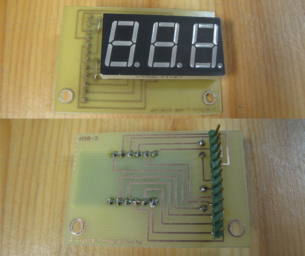
The three digit display board. It uses a very bright display chip from eBay.
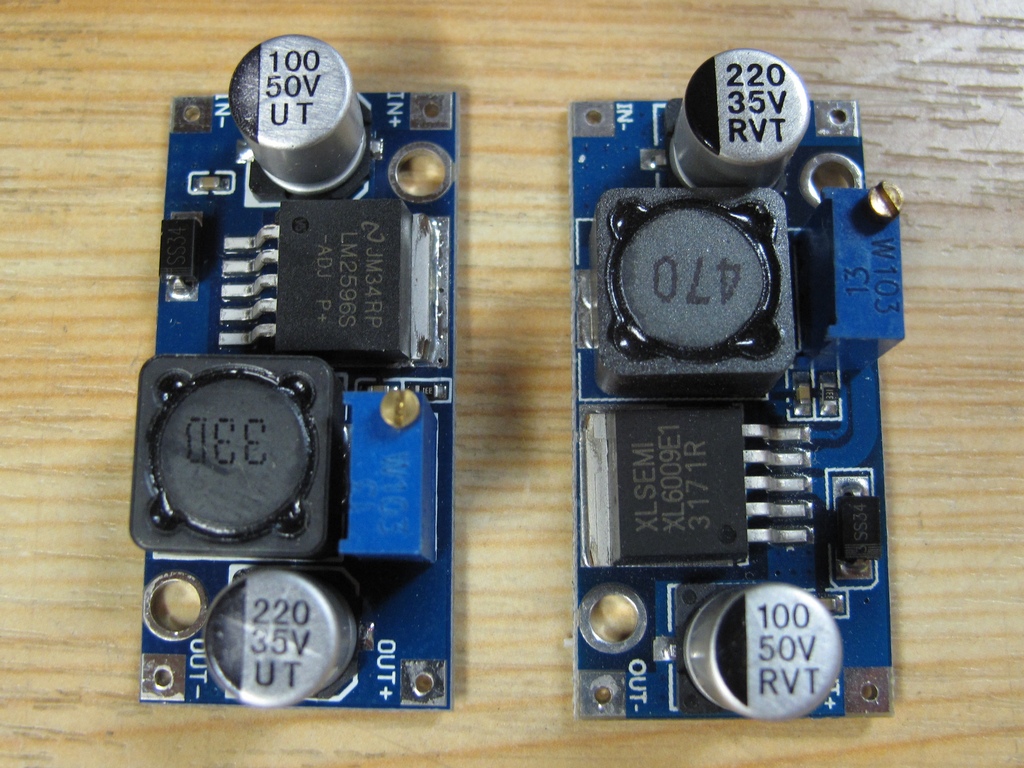
The control & driver boards run at 5 VDC and the RF switches require 28 VDC, so in order to use a single common external 12 VDC adapter the voltages had
to be generated using a step down converter and a step up converter. These come very cheap from eBay and work fine.
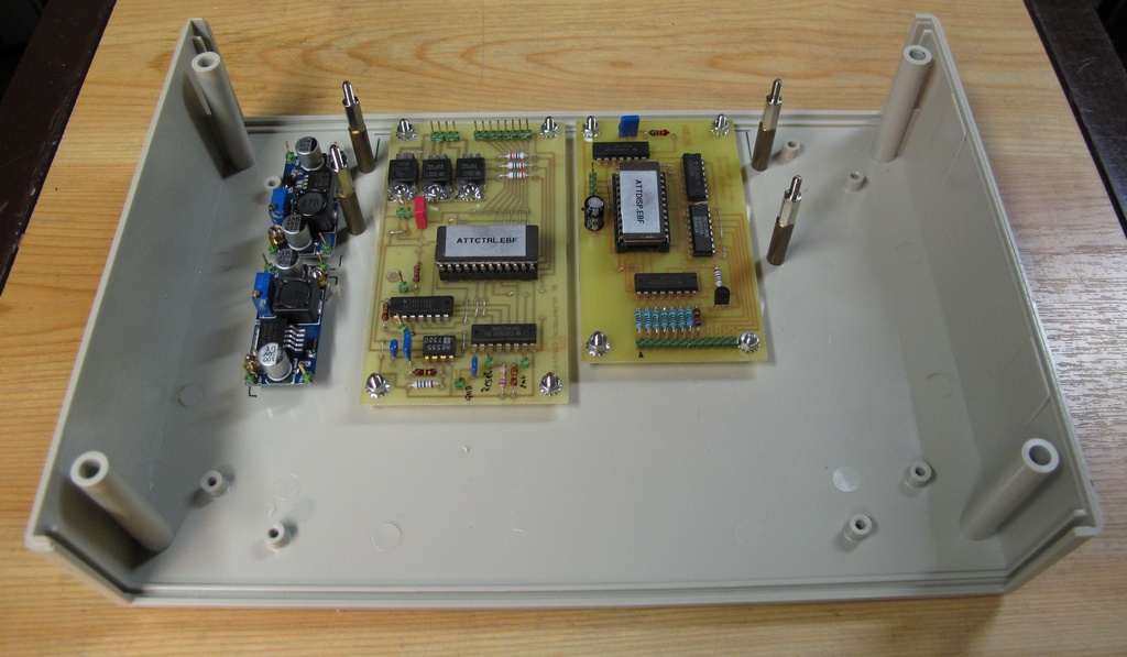
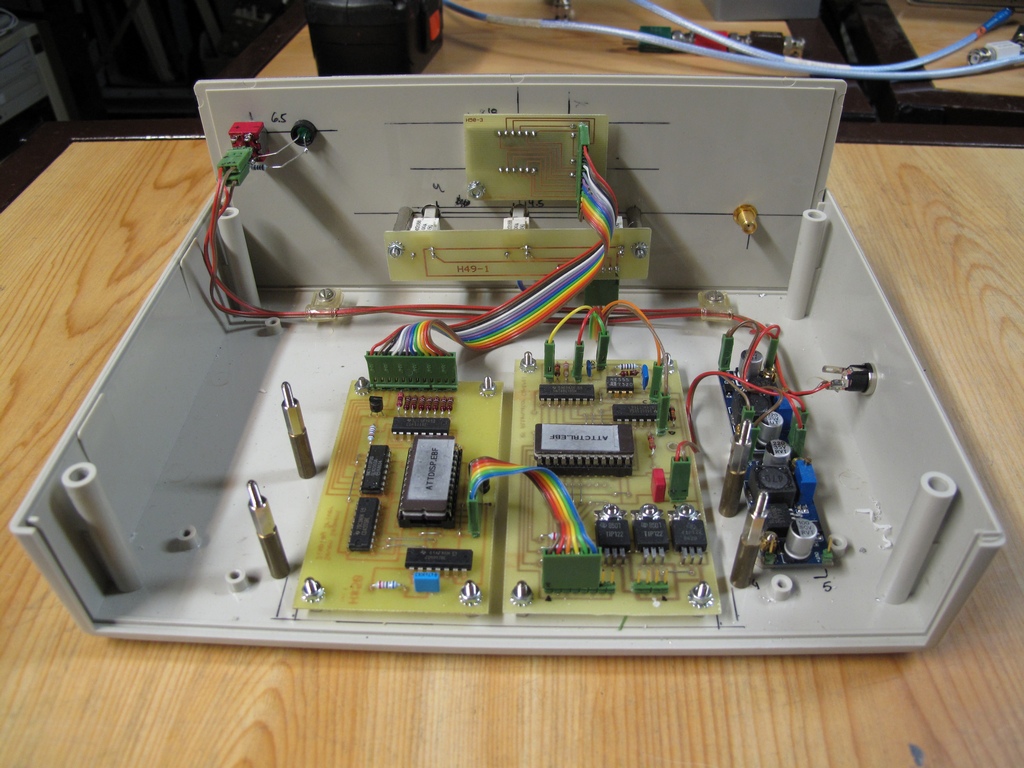
The boards installed in the case.
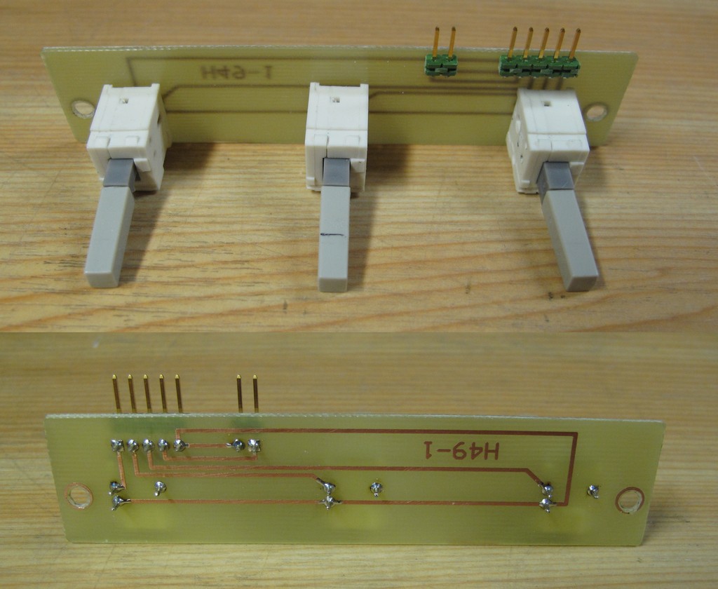
I used push button switches from a scrapped 2430.
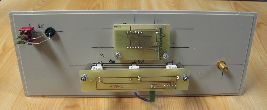
The front panel from the inside ....
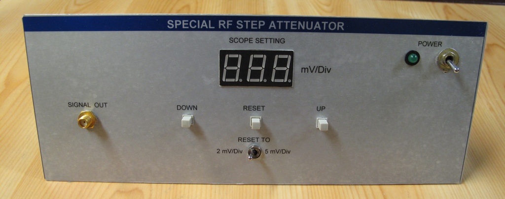
.... and from the outside.
The almost finished inside of the box ....
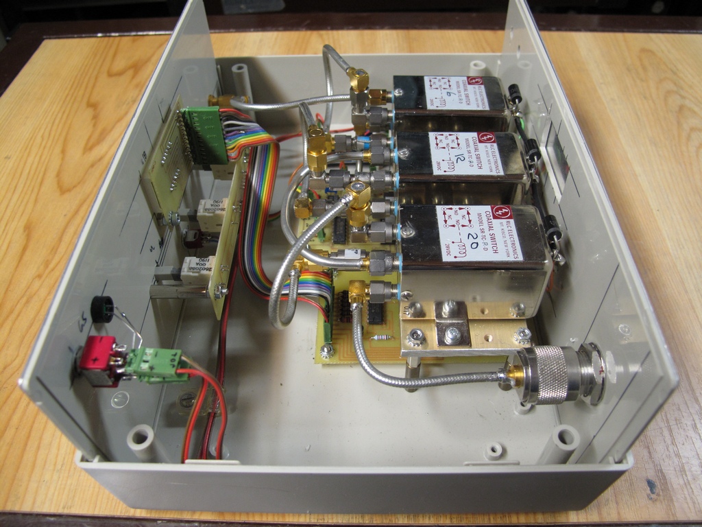
.... and with switches and rear panel in place.
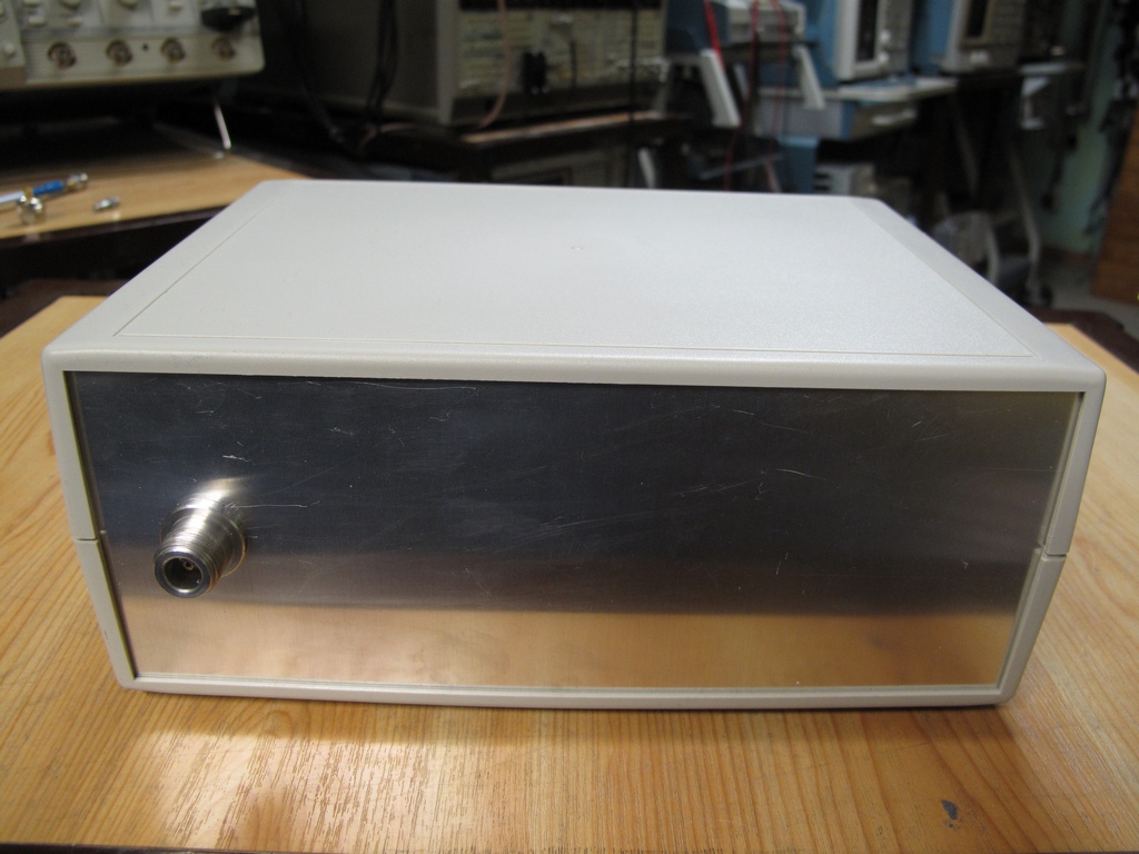
The rear panel. I chose to use an N-connector instead of SMA to increase the mechanical stability since here is where the CG head will connect.
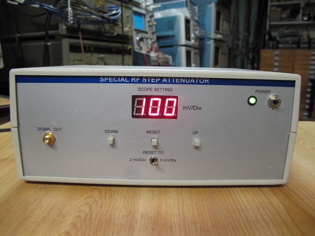
The finished box.
Email me with comments. /Håkan
Home / Go back