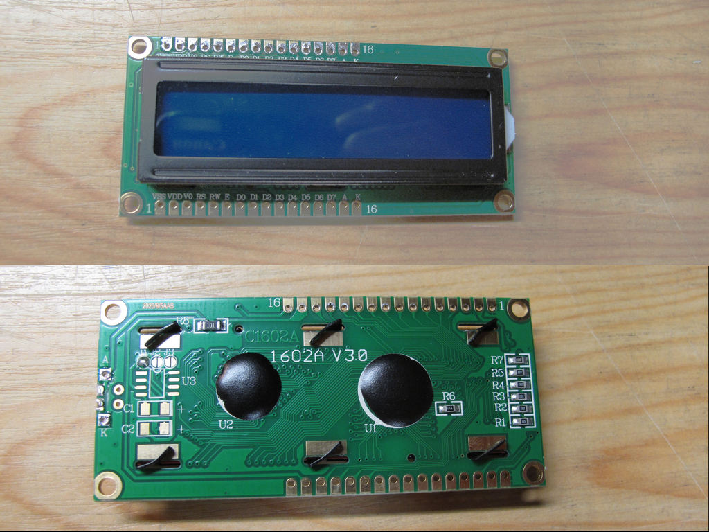
The new display. It differs from the original in how contrast and backlight are controlled.
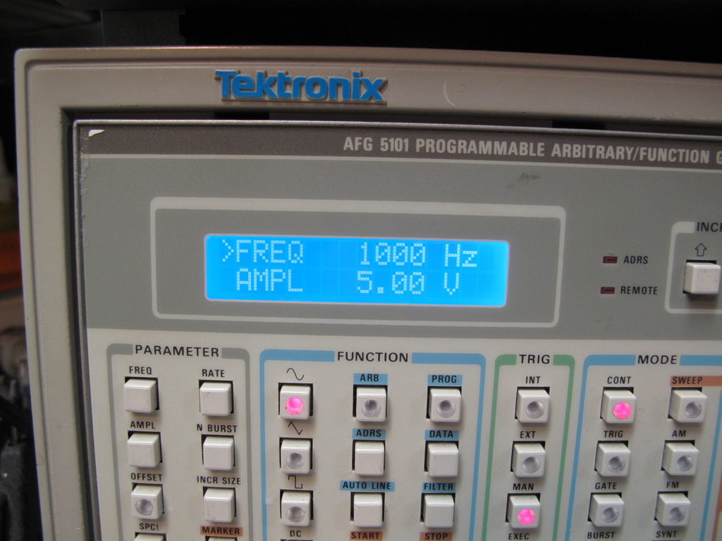
Replacing the Display in an AFG5101
This is how I replaced the dull and low contrast display with a semi compatible
blue/white display. These could be purchased fairly cheap from several places
like
AliExpress or eBay. The P/N is 1602 or 1602A. It is semi compatible
because the data part is compatible but the contrast and backlight controls have
to be modified.
The new
display. It differs from the original in how contrast and backlight are
controlled.
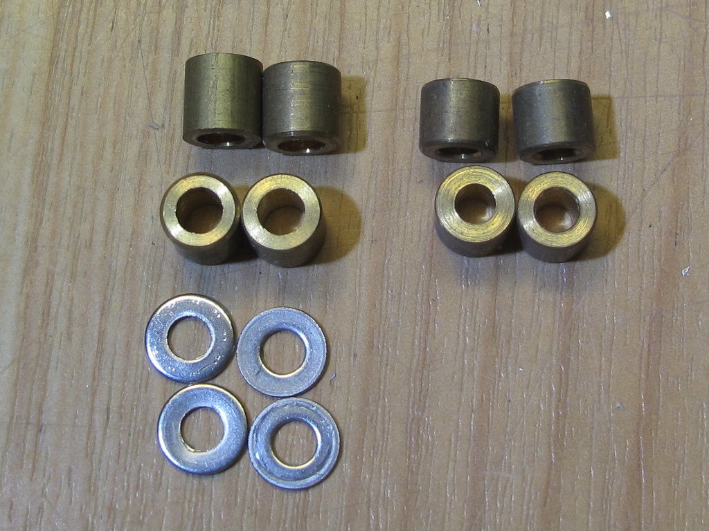
The new
display is about 1.5mm higher than the original. The original spacers are 6 mm +
a 0.5mm washer. I had several 5mm spaces so when using them
instead of the
original spacers & washers the distance from the top of the display to the front
panel would be the same.
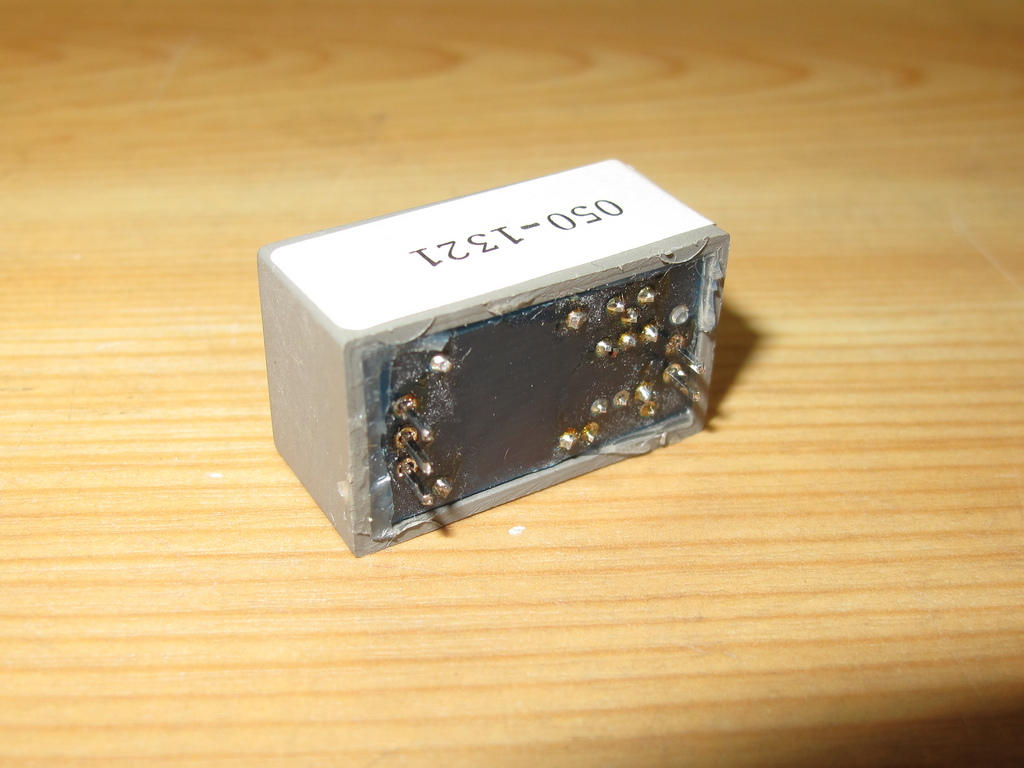
The original
backlight is controlled with a special module located on the front pamel board
and it is not compatible with the new display. In fact the backlight
LED in
the new display could be destroyed by this module if connected to the same pads
as the original which I found out the hard way. The original backlight
could
be changed from the front panel but it didn't work very well so it's not a big
loss to discard this module.
Although the
schematic looks like the contrast could also be chamged I have not found a way
to do that in the original setup.
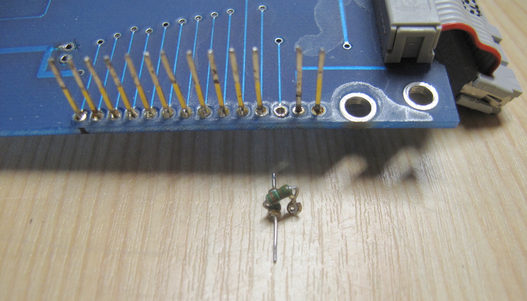
On the connector between the display and
the front panel board there was a voltage divider network, not shown in the
manual, between the contrast pin and
+5V which I removed and replaced with a
common pin.
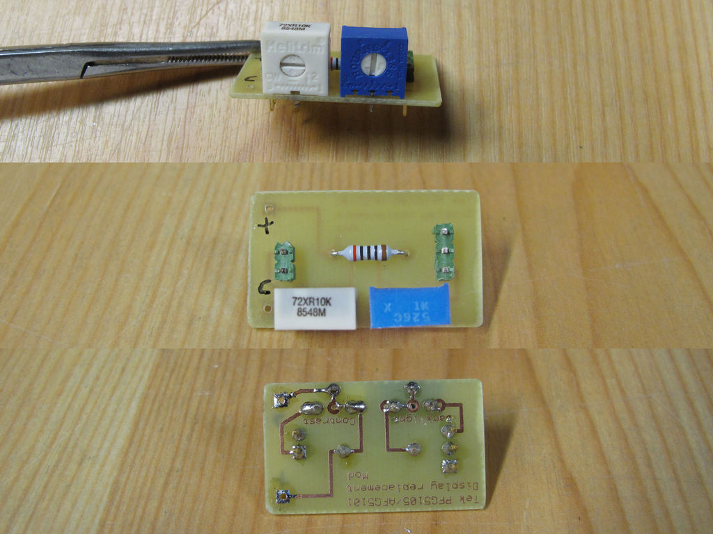
So I made a
small circuit board with trim pots for contrast and backlight. It fits in the
holes vacated when the module mentioned above was removed.
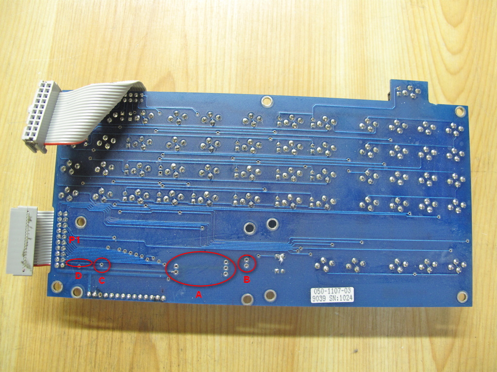
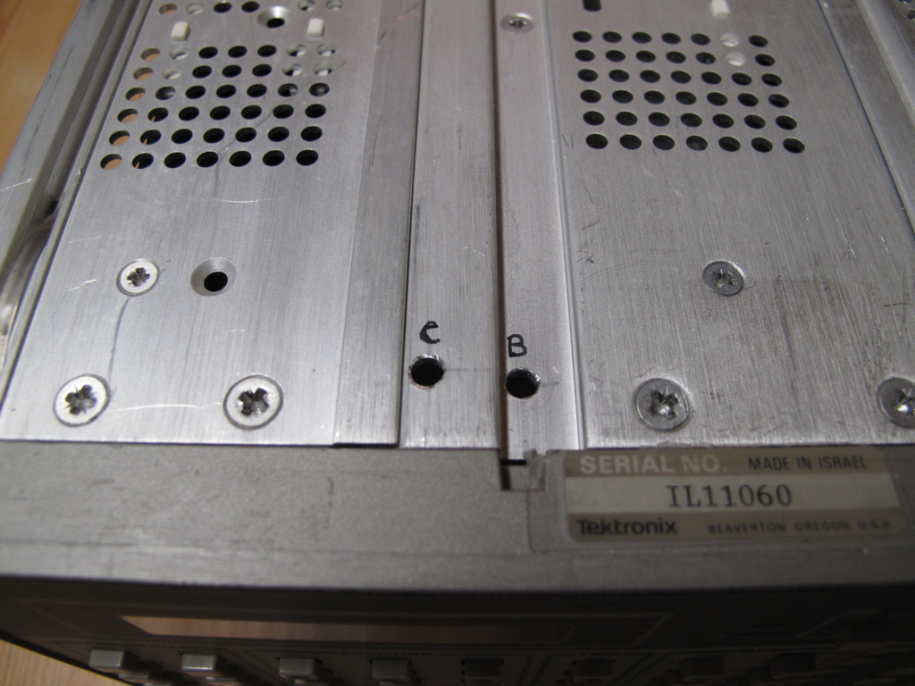
A: The holes
from the original module where the new circuit board is connected.
B: The holes to which the backlight
LED of the new display is connected.
C: Here is where the output of the contrast
pot connected.
D: This run must be cut.
In addition the new circuit board
is also conncted to +5V which is on pin 20 of P1 (bottom left) and to ground via
several of the holes of A.
The pin count of P1 is
from 1 to 10 going up from the bottom of the left row and then 11 to 20 going
down on the right row rather than the conventional
way of count on a IDC
connector which is odd numbers one one row and even numbers on the other row.
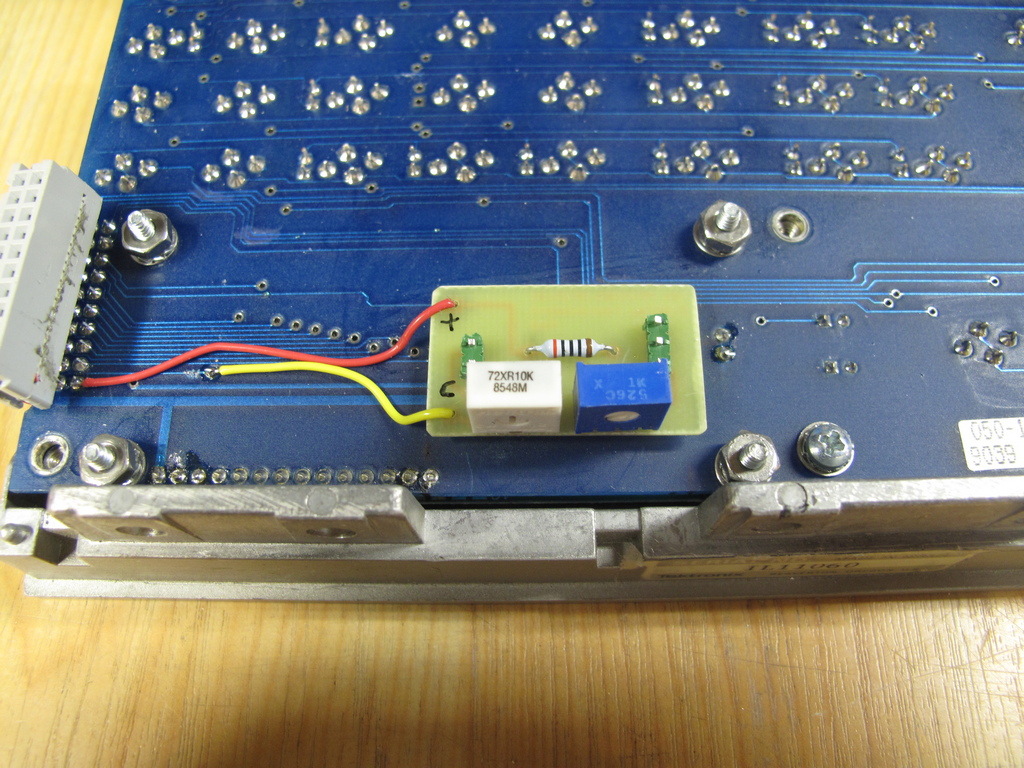
The new
circuit board in place on the front panel board .....
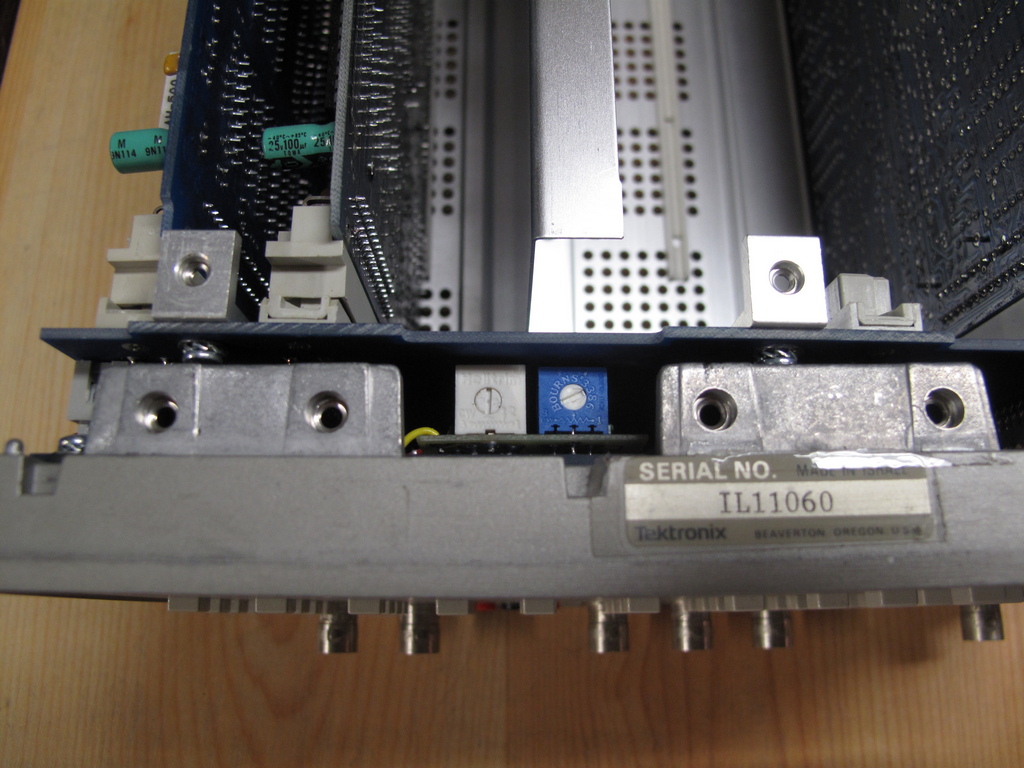
with front
panel intstalled .....
and finally
with the frames installed and holes drilled for access to the pots from the
outside.
The final
look.
Email me with comments. /Håkan
Home / Go back