Building an accurate Frequency Standard
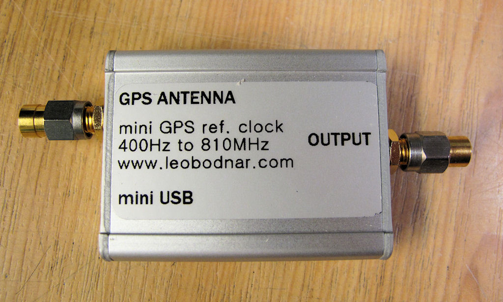
I purchased this little Mini Precision GPS Reference Clock from Leo Bodnar Electronics at a very reasonable price.
It works very well and to comply with the rest of my test equipment I wanted to enclose it into a TM500 plug-in.
This is what it looks like.
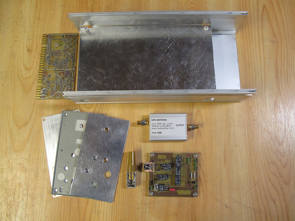
The hardware came from various scrapped plug-ins. I made a aluminum sub frame to replace the original circuit board and the interface connector was cut off
from a scrapped board. A front panel and a power supply circuit board was made .
The GPS receiver has LED indicator in the case. I didn't want to open it to get access to the drive signal so instead I used an LDR (Light Dependent Resistor)
in the case of an old probe comp box to pick up the light from the LED which the front panel LED is driven from.
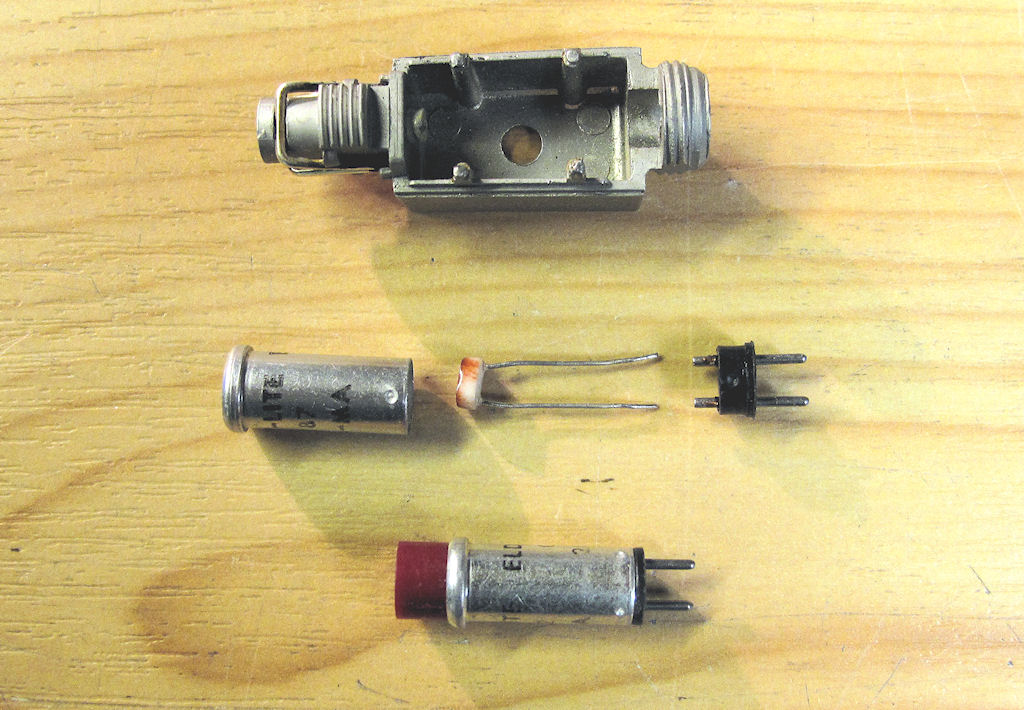
I inserted the LDR into the case on an old Tek indicator light which then was mounted inside the probe comp box.
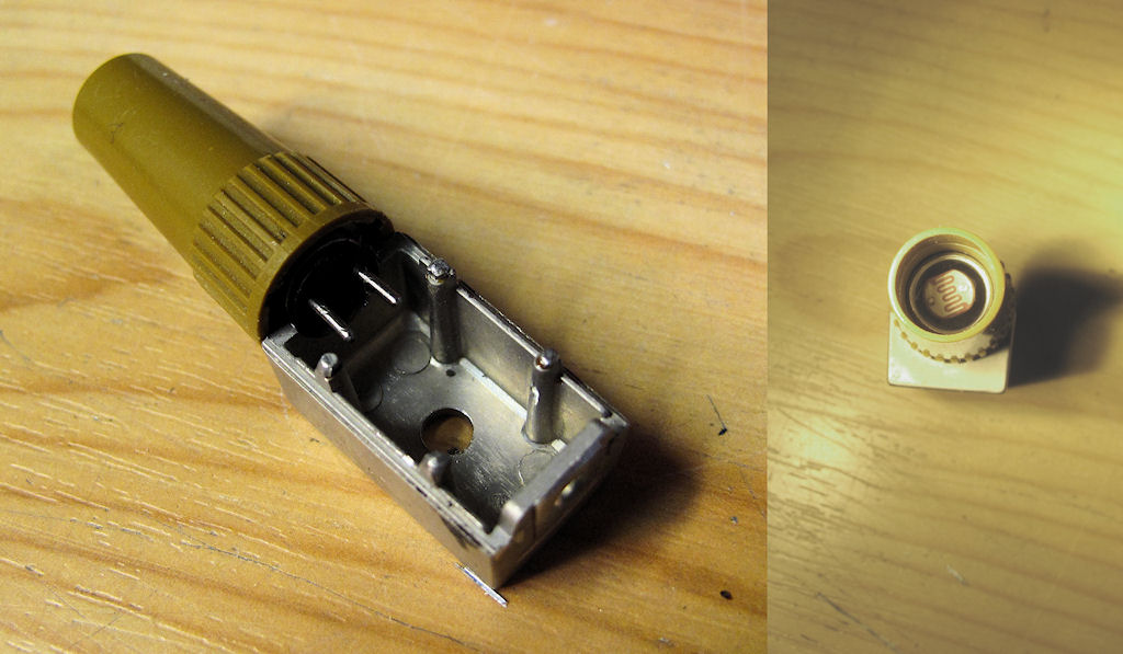
The finished light sensor assy. One end of the comp box was sawed off.
The unit should be able to be powered from either the front panel USB connector or internally from the TM500 main frame.
Obviously these power sources should not be allowed to interfere with each other. The power supply circuit contains a set of relays set up so if one of the
power sources is active the other will have no effect until both are turned off.
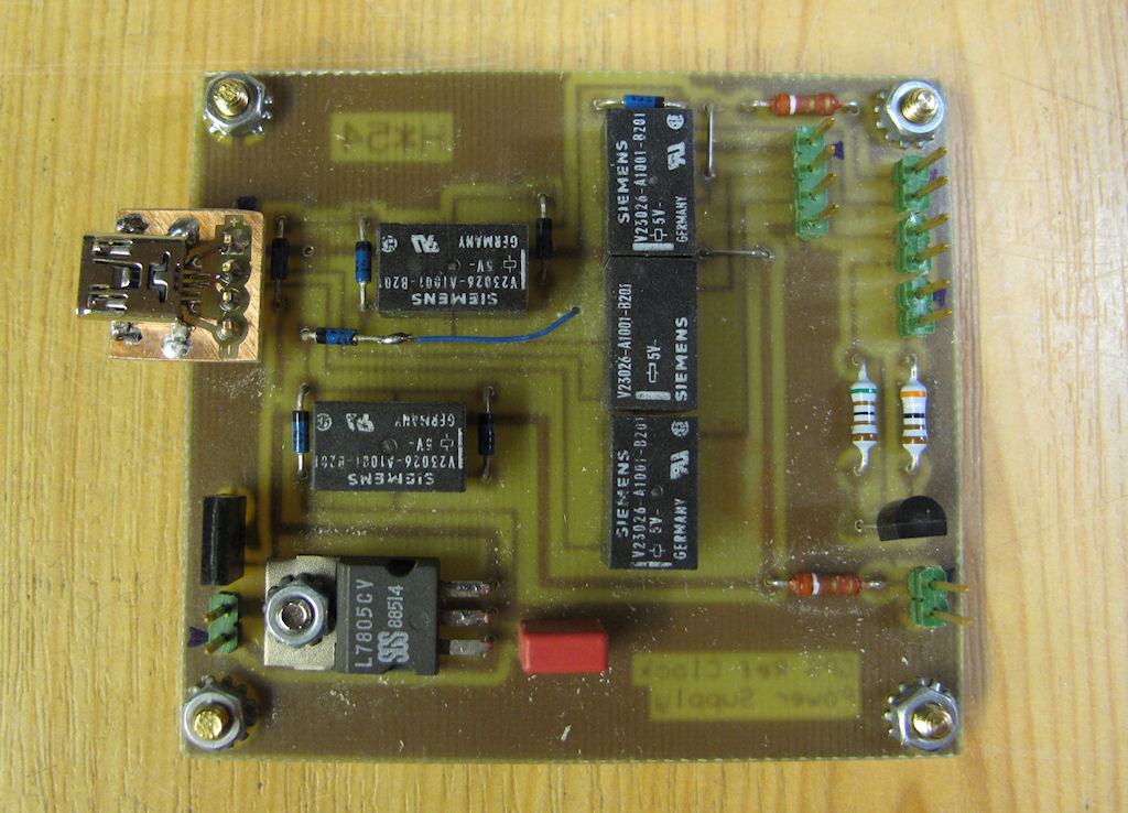
The circuit board. Schematics here.
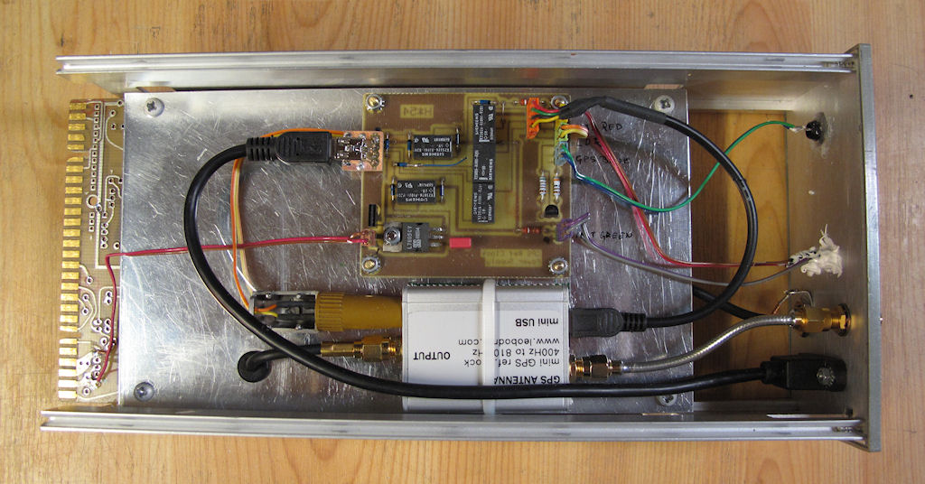
The finished plug-in from the component side .......
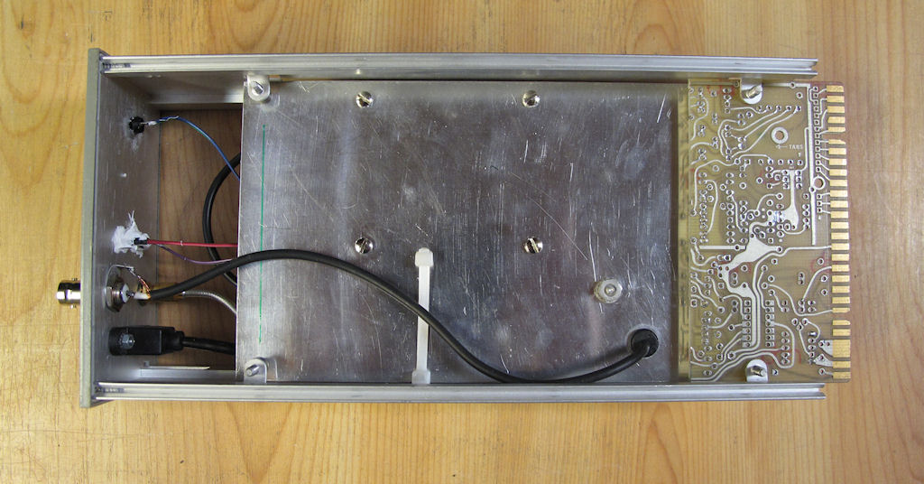
.... from the reverse side ...
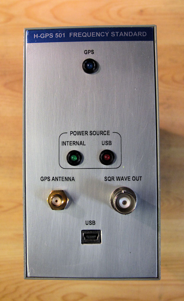
... and from the front. I didn't bother to use the latch / release knob assy since it's supposed to be sitting in the same main frame all the time.
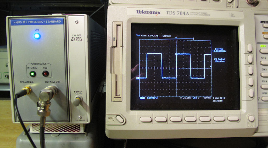
Up and running. The GPS LED flashes until enough satellites has been found and it unit locks. The LED then is steady on.
Email me with comments. /Håkan
Home / Go back