Installing an LCD display in a TDS544A
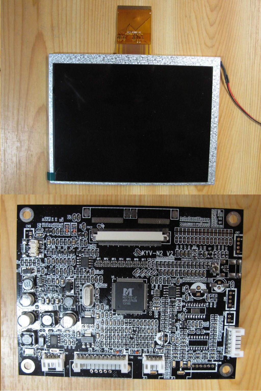
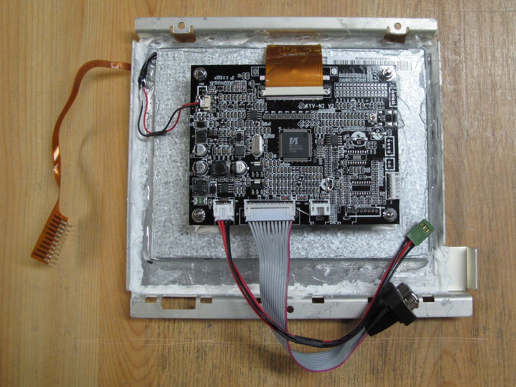
The LCD kit purchased from eBay. There is also a small circuit board with control switches, not shown here.
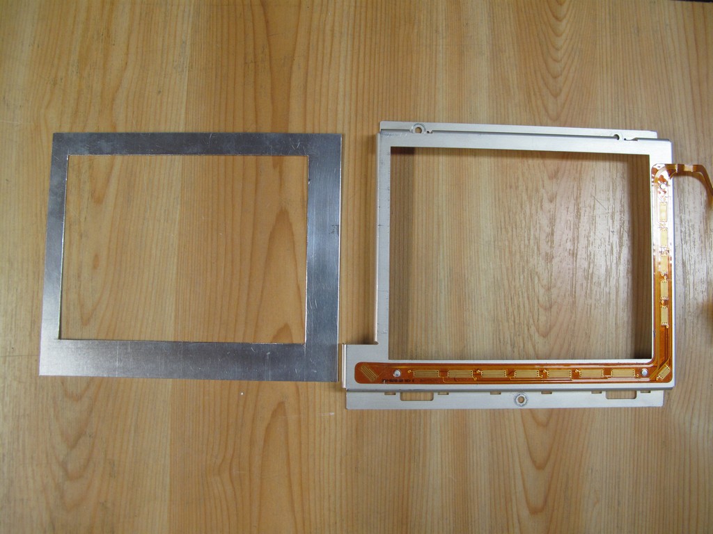
Made a new frame of thin aluminum to be fitted between the LCD and the original display frame. It was painted flat black.
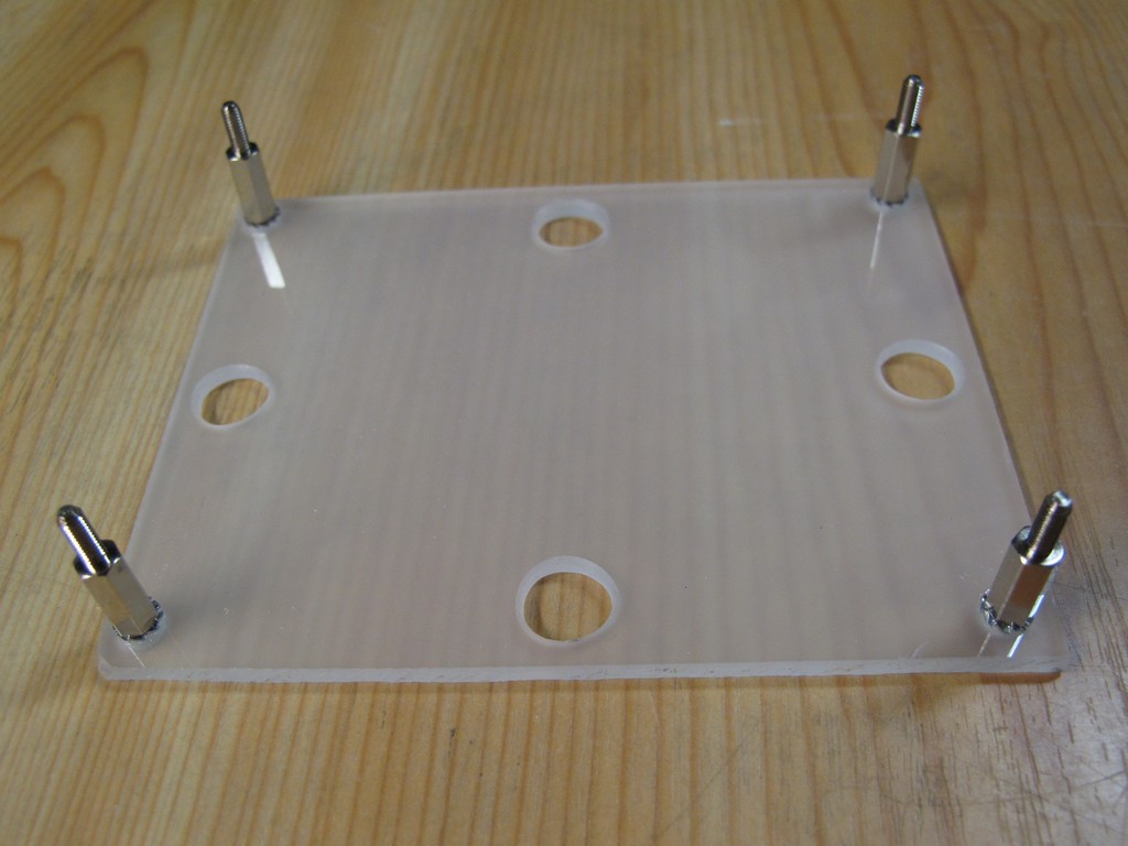
Made a holder for the LCD circut board.
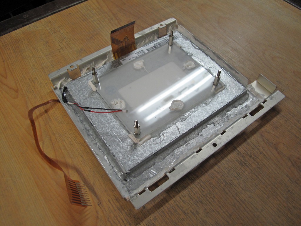
The LCD was glued to the new frame using epoxy, the new frame was glued to the original frame and the circuit board holder was glued to the back of the LCD.
The completed assy.
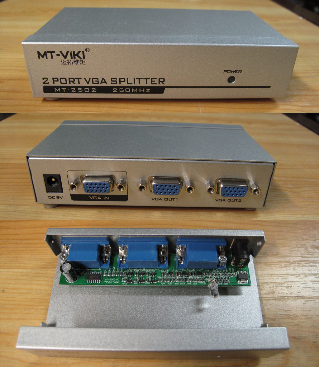
The LCD assy uses the VGA signal from the scope. In order to preserve the VGA output on the rear I purchased a VGA splitter, also from eBay.
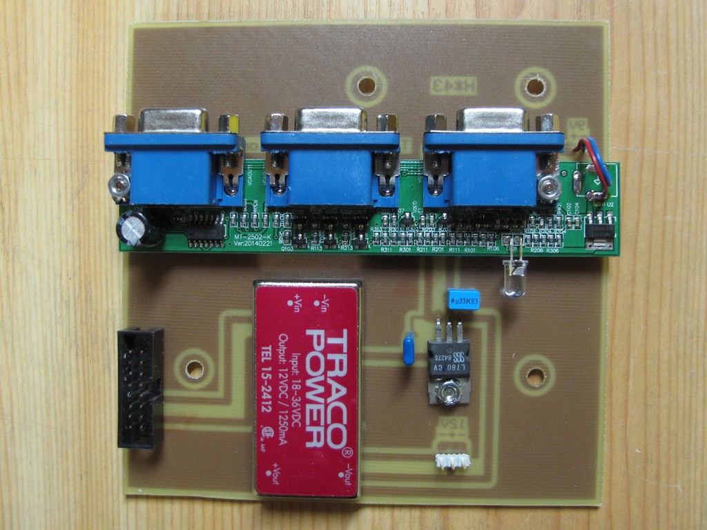
Made a circuit board which connects to the original mounts in the TDS scope. It also have the power input connector in the same location as the original CRT
driver board. It uses the +25V in and outputs +12V to the LCD driver and +9V to the VGA splitter.
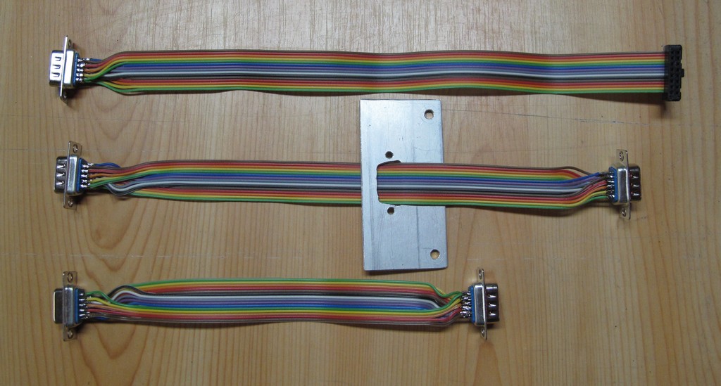
Three special cables had to be
made. The bracket on the one in the middle connects to the front of the scope
close to the LCD display.
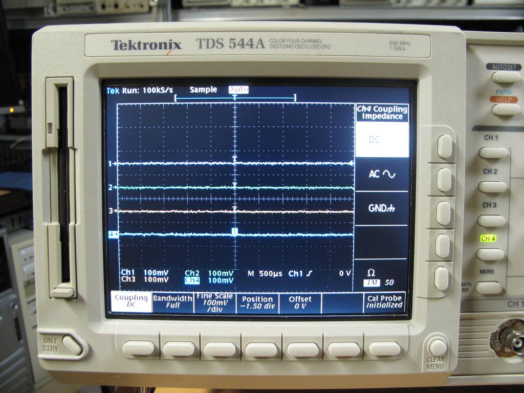
Measurements here.
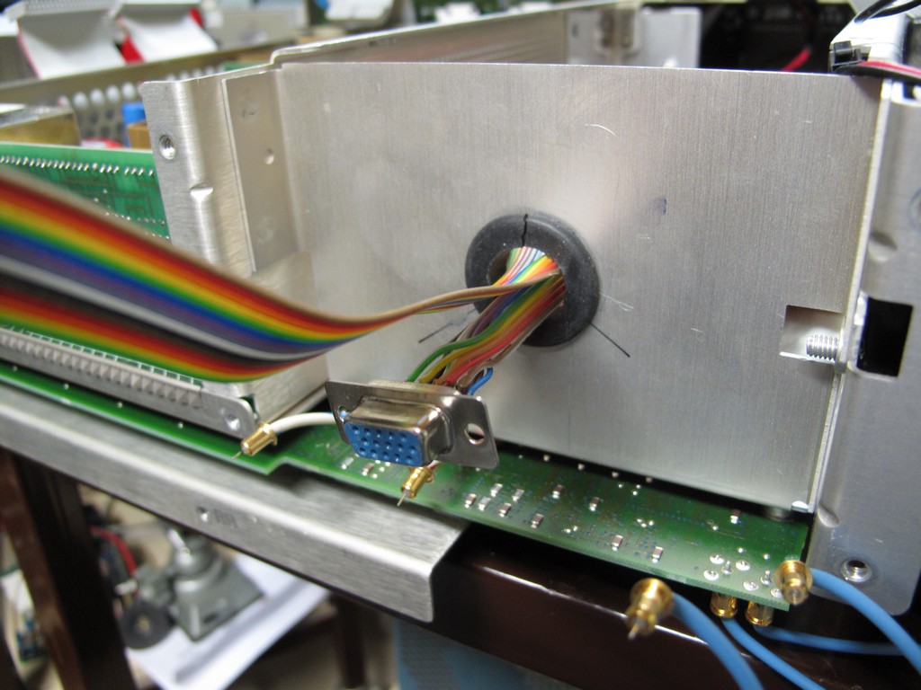
A hole had to be made in the TDS frame in order to route the VGA in and VGA out cables to the splitter. On the picture the TDS rear panel has been removed.
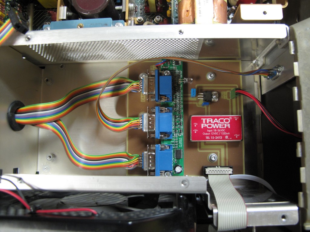
The circuit board, cables and bracket in place.
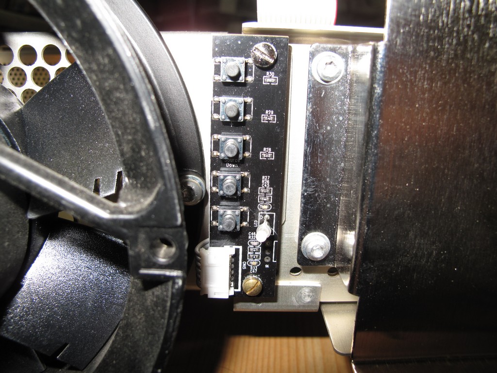
The small control baord could fit between the fan and the floppy drive using an existing hole for the lower mount. A new hole had to be drilled for the upper
mount. If the scope uses the newer square fan the next hole to the right could be used.
The finished display. It doesn't line up perfectly with the bezel buttons but good enough.
Email me with comments. /Håkan